


 You are here; Home / Resources /FAQ
What is a battery?
Battery Definition
Lithium-ion Polymer
Lithium-ion polymer batteries use liquid Lithium-ion electrochemistry in a matrix of ion conductive polymers that eliminate free electrolyte within the cell. The electrolyte thus plasticizes the polymer, producing a solid electrolyte that is safe and leak resistant. Lithium polymer cells are often called Solid State cells.
Because there's no liquid, the solid polymer cell does not require the heavy protective cases of conventional batteries. The cells can be formed into flat sheets or prismatic (rectangular) packages or they can be made in odd shapes to fit whatever space is available. As a result, manufacturing is simplified and batteries can be packaged in a foil. This provides added cost and weight benefits and design flexibility. Additionally, the absence of free liquid makes Lithium-ion polymer batteries more stable and less vulnerable to problems caused by overcharge, damage or abuse.
Solid electrolyte cells have long storage lives, but low discharge rates.
There are some limitations on the cell construction imposed by the thicker solid electrolyte separator which limits the effective surface area of the electrodes and hence the current carrying capacity of the cell, but at the same time the added volume of electrolyte provides increased energy storage. This makes them ideal for use in high capacity low power applications.
Despite the above comments there are some manufacturers who make cells designated as Lithium polymer which actually contain a liquid or a gel. Such cells are more prone to swelling than genuine solid polymer cells.
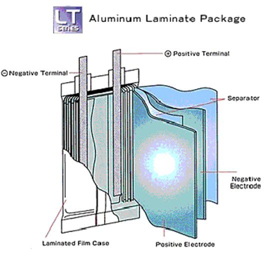
Pouch cell - Also known as Lipo cells
Vulnerable, Inexpensive, Design freedom on dimensions, Difficult packaging, High energy density but reduced by support packaging needed, Prone to swell and leak, Less danger of explosion (cell bursts), Good heat dissipation, Made in very high volumes, Economical for small volumes, Sizes up to 240 Ah
Pouch casings are typically used for Lithium Polymer cells with solid electrolytes, providing a low cost "flexible" (sometimes in unintended ways) construction. The electrodes and the solid electrolyte are usually stacked in layers or laminations and enclosed in a foil envelope. The solid electrolyte permits safer, leak-proof cells. The foil construction allows very thin and light weight cell designs suitable for high power applications but because of the lack of rigidity of the casing the cells are prone to swelling as the cell temperature rises. Allowance must be made for the possibility of swelling when choosing cells to fit a particular cavity specified for the battery compartment. The cells are also vulnerable to external mechanical damage and battery pack designs should be designed to prevent such possibilities.
The Honcell example illustrated uses spiral wound electrodes and a solid polymer electrolyte.
This construction, using stacked electrodes is suitable for making odd shaped cells but few applications make use of this opportunity.
Battery Abbreviations
Abbreviations
$ Dollar in US currency
18650 Li-ion cylindrical cell format measuring 18mm times 65mm
A Ampere (electrical)
AC Alternating current
ADAC Allgemeiner Deutscher Automobil-Club (German automobile club)
AFC Alkaline fuel cell
AGM Absorbent Glass Mat (battery)
AGV Automatic Guided Vehicle
Ah Ampere-hour
APU Auxiliary Power Unit
BAPCO Business Applications Performance Corporation
Bar Unit ofpressure; 1 bar = 100kPa; 1 bar = 14.503psi
bbl Measurements of liquid, 1 barrel = 42 US gallons (35 Imperial gallons), 159 liters
BCG The Boston Consulting Group
BCI Battery Council International
BMS Battery management system
BMW Bavarian Engine Works (Bayerische Motoren Werke)
BTU British Thermal Unit; 1 BTU = 1,054 joules; 1 BTU = 0.29Wh
C Celsius, Centigrade (temperature)
cal Calorie; 1cal = 4.18 joules; 1cal = 4.18 watt/s; 1,000 joules = 0.277Wh
CARB California Air Resources Board
CCA Cold cranking amps at –18°C (0°F). The norms differ as follows:
BCI discharges battery at CCA-rate for 30s; battery at or above 7.2V passes
IEC discharges battery at CCA-rate for 60s; battery at or above 8.4V passes
DIN discharges battery at CCA-rate for 30s and 150s; battery at or above 9V and 6V respectively passes
CCCV Constant current constant voltage (charge method)
CCV Closed circuit voltage (battery under charge or discharge)
CDMA Code Division Multiple Access (cell phones)
CEC Certificate of Equivalent Competency (International regulations)
CID Circuit interrupt device
CIPA Camera and Imaging Products Association
CL Current limiting (as in charging a battery)
CNG Compressed natural gas
CNT Carbon nanotube
CPU Central processing unit
Co Cobalt (metal)
COC Certificate of Competency
CO2 Carbon dioxide
CPR Cardiopulmonary resuscitation
C-rate Discharge rate of a battery
DC Direct current
DGP Dangerous Goods Panel
DIN Deutsches Institut für Normung (German Institute for Standardization)
DLC Double-layer capacitor
DMFC Direct Methanol Fuel Cell
DoD Depth of discharge
DOE Department of Energy (US)
DOT Department of Transportation (US)
DSP Digital signal processor
dT/dt Delta Temperature over delta time (charge method)
EBM Electronic battery monitor
ect. Et cetera. Latin: And so forth
EDTA Crystalline acid
EIS Electrochemical Impedance Spectroscopy
ELC Equivalent lithium content
EMF Electromagnetic field
EMF Electromotive force
EPA Environmental Protection Agency (US)
EV Electric vehicle
F Fahrenheit (temperature)
f Farad (unit of capacitance)
FAA Federal Aviation Administration
FC Fuel cell
FCVT FreedomCAR & Vehicle Technologies (US Department of Energy)
Foot/’ Foot (dimension) 1’= 12”; 1’ = 0.3048m; 1’times 3.28 = 1m
g Gram; 1g = 0.035oz; 1g times 28.35 = 1oz
GSM Global System for Mobile Communications (cell phones)
h Hour (time)
HEV Hybrid electric vehicle
hp Horsepower (power) 1hp = 745.7 watts
Hz Hertz (electrical frequency)
I Current(electrical)
i.e. Id est. Latin: That is
IATA International Air Transport Association
IC Integrated circuit (chip)
IC Internal combustion (engine)
ICAO International Civil Aviation Organization
IEC International Electrochemical Commission
Inch/“ Inch; 1”= 25.4mm; 1” = 0.0254 meter; 1”times 39.3 = 1m
IPF Interfacial protective film
IPP IECaircraft battery rating (0.3/15s power discharge)
IPR Aircraft battery rating according to IEC (15s power discharge)
IS Intrinsic safety (used on batteries)
J Joule, 1J = 1A at 1V for 1s = 1 watt/s; 1J = 0.238calorie/s
kg Kilogram; 1kg = 0.45 pound; 1kg times 2.2 = 1 pound
kJ Kilo-Joule; 1kJ = 0.277Wh
km Kilometer; 1km = 0.621 miles; 1km times 1.60 = 1 mile
kN Kilo-Newton (law of motion) 1N = 1kg m/s2
kPa Kilo-Pascal (pressure); 1kPa = 0.01 bar; 1kPa = 0.145psi
kW Kilowatt (electrical energy); 1kWh = 3.6MJ; 1MJ = 860kcal = 238cal/s
kWh Kilowatt-hour (electrical power)
L Inductance (electrical coil)
lb Pound (weight, from Roman libra) 1 lb times 0.45 = 1kg
LCD Liquid crystal display
LCO Lithium cobalt oxide
LED Light emitting diode
LFP Lithium-iron-phosphate
LFPT Low frequency pulse train (method to test a battery)
LiCoO2 Lithium-ion-cobalt-oxide
LiFePO4 Lithium-iron-phosphate-oxide
Li-ion Lithium-ion battery (short form)
LiMn2O4 Lithium-ion-manganese-oxide
LiNiCoAlO2 Lithium-ion-nickel-cobalt-aluminum-oxide
LiNiMnCoO2 Lithium-on-nickel-manganese-cobalt-oxide
Li5Ti5O13 Lithium-titanate-oxide
L/km Liter per kilometer
LMO Lithium-manganese-oxide
LTO Lithium-titanate
m Meter (dimension) 1m = 3.28 feet; 1m times 0.30 = 1 foot
mAh Milliampere-hours
MCFC Molten carbonate fuel cell
Microfarad [µF] Capacitor rating, one-millionth 10-6 of a farad)
Min Minute (time)
mm Millimeter (dimension) 1mm = 0.039”; 1mm times 25.4 = 1”
Mn Manganese(chemical element used in batteries)
mpa Mega-Pascall unit of pressure
Mpg Miles per gallon
ms Millisecond, one-thousand of a second (10-3).
MW Megawatt (power)
N Newton (law of motion) 1N = 1kg m/s2 (force required to accelerate 1kg at 1m/s)
NaS Sodium-sulfur (battery)
NASA National Aeronautics and Space Administration
NCA Lithium-ion battery with nickel, cobalt, aluminum cathode
NCV Net calorific value (1 food calorie = 1.16 watt-hour)
NDV Negative delta V (full-charge detection)
NG Natural gas, consumption measured in joules (1,000 joules = 0.277Wh)
NiCd Nickel-cadmium (battery)
NiFe Nickel-iron (battery)
NiH Nickel-hydrogen battery
NiMH Nickel-metal-hydride (battery)
NiZn Nickel-zinc (battery)
NMC Lithium-ion with nickel, manganese, cobalt cathode
NRC National Research Council
NTC Negative temperature coefficient
OCV Open circuit voltage
OEM Original equipment manufacturer
Oz Ounce; 1 oz = 28 grams; 1 oz times 0.035 = 1 gram
PAFC Phosphoric acid fuel cell
PC Personal computer
PEM Proton exchange membrane (fuel cell), also PEMFC
PEMFC Proton exchange membrane fuel cell, also PEM
pf Pico-farad (capacitor rating, one-trillionth 10-12 of a farad)
pf Power factor (ratio of real power to the apparent power on AC)
PHEV Plug-in hybrid electric vehicle
PRBA Portable Rechargeable Battery Association
psi Pound per square inch (pressure) 1psi = 0.145kPa; 1psi times 6.89 = 1kPa
PTC Positive temperature coefficient
PTC Over-voltage protection (batteries, motors, speakers)
QA Quality assurance
Qi Standard on inductive charging by Wireless Power Consortium (WPC)
Q-Mag™ Quantum magnetic battery analysis (Cadex trademark)
R Resistor (electrical)
RBRC Rechargeable Battery Recycling Corporation
RC Remote control (hobbyist)
RC Reserve capacity of starter battery. Conversion formula:. RC divided by 2 plus 16 = Ah
R&D Research and development
RPM Revolution per minute
s Second (time)
SAE Society of Automotive Engineers, founded early in 1900 by US auto manufacturers
SBS Smart Battery System
SEI Solid electrolyte interphase (Li-ion)
SG Specific gravity (acid density of electrolyte)
SLA Sealed lead acid (battery)
SLI Starter-light-ignition (battery), also knows as starter battery
SMBus System Management Bus (smart battery)
SoC State-of-charge
SoF State-of-function
SOFC Solid oxide fuel cell
SoH State-of-health
UL United Laboratories (product safety testing and certification)
UPS Uninterruptible power supply
USB Universal Serial Bus (data)
V Voltage (electrical)
VA Volt-ampere (similar to watt with true current flow in a reactive load)
VAC Voltage with alternating current (grid)
VL Voltage limiting (as in charging a battery)
VRLA Valve regulated lead acid (battery)
W Watt (electrical energy; voltage times current = watts)
Wh Watt-hour (electrical power; watts times h = Wh); 1Wh = 860 cal/h = 0.238cal/s
Wh/kg Watt-hour per kilogram (measurement of specific energy)
Wh/km Watt-hour per kilometer
Wh/l Watt-hour per litter (measured in energy density)
Wi-Fi Wireless fidelity (network)
W/kg Watt per kilogram (measurement of specific power)
WPC Wireless Power Consortium
WW World War
Z Impedance (reactance-based resistance, frequency dependent)
ZEBRA Zeolite Battery Research Africa Project (battery)
Cell Nomenclature
There is considerable confusion about naming standards for cells with different systems used in Europe, the USA and Japan as well as manufacturers ' own standards.
One convention is two letters followed by a series if numbers.
The first letter represents the cell chemistry. The second letter represents the shape of the cell.
The numbers represent the dimensions of the cell in millimetres. For cylindrical cells the first two digits are the diameter and the remaining digits the length. For prismatic cells the first two digits represent the thickness, the second pair the height and the last pair the width.
Because of the plethora of "standards" the only safe course in identifying a cell is to consult the manufacturers' data sheets.
Examples
Common Primary Cells
See Battery Case Sizes for dimensions of common primary cells.
Cylindrical Cells
LC18650 is a common Li-ion cell in a Cylindrical can Size (diameter18mm height 65.0mm)
See Cylindrical Cell Sizes for a listing of typical cylindrical cell sizes and capacities
Prismatic Cells
LP083448 is a Li-ion cell in a Prismatic can Dimensions( thickness 8mm height 48mm width 34 mm)
See Prismatic Cell Sizes for a listing of typical prismatic cell sizes and capacities.
See Power Cell Sizes for examples of high power prismatic cells. (High power cylindrical cells are also available)
See also Battery Pack Design
Cell Balancing
Cell Balancing
In multi-cell batteries, because of the larger number of cells used, we can expect that they will be subject to a higher failure rate than single cell batteries. The more cells used, the greater the opportunities to fail and the worse the reliability.
Batteries such as those used for EV and HEV applications are made up from long strings of cells in series in order to achieve higher operating voltages of 200 to 300 Volts or more are particularly vulnerable. The problems can be compounded if parallel packs of cells are required to achieve the desired capacity or power levels. With a battery made up from n cells, the failure rate for the battery will be n times the failure rate of the individual cells.
All cells are not created equal
The potential failure rate is even worse than this however due to the possibility of interactions between the cells. Because of production tolerances, uneven temperature distribution and differences in the ageing characteristics of particular cells, it is possible that individual cells in a series chain could become overstressed leading to premature failure of the cell. During the charging cycle, if there is a degraded cell in the chain with a diminished capacity, there is a danger that once it has reached its full charge it will be subject to overcharging until the rest of the cells in the chain reach their full charge. The result is temperature and pressure build up and possible damage to the cell. With every charge - discharge cycle the weaker cells will get weaker until the battery fails. During discharging, the weakest cell will have the greatest depth of discharge and will tend to fail before the others. It is even possible for the voltage on the weaker cells to be reversed as they become fully discharged before the rest of the cells also resulting in early failure of the cell. Various methods of cell balancing have been developed to address this problem by equalising the stress on the cells.
Self Balancing
Unbalanced ageing is less of a problem with parallel chains which tend to be self balancing since the parallel connection holds all the cells at the same voltage and at the same time allows charge to move beween cells whether or not an external voltage is applied. There can however be problems with this cell configuration if a short circuit occurs in one of the cells since the rest of the parallel cells will discharge through the failed cell exacerbating the problem.
See Interactions Between Cells for more details.
The problems caused by these cell to cell differences are exaggerated when the cells are subject to the rapid charge and discharge cycles (microcycles) found in HEV applications.
While Lithium batteries are more tolerant of micro cycles they are less tolerant of the problems caused by cell to cell differences.
Because Lead acid and NiMH cells can withstand a level of over-voltage without sustaining permanent damage, a degree of cell balancing or charge equalisation can occur naturally with these technologies simply by prolonging the charging time since the fully charged cells will release energy by gassing until the weaker cells reach their full charge. This is not possible with Lithium cells which can not tolerate over-voltages. Although the problem is reduced with Lead acid NiMH batteries and some other cell chemistries, it is not completely eliminated and solutions must be found for most multicell applications.
No matter what battery management techniques are used, the failure rate or cycle life of a multicell battery will always be worse than the quoted failure rate or cycle life of the single cells used to make up the battery.
Once a cell has failed, the entire battery must be replaced and the consequences are extremely costly. Replacing individual failed cells does not solve the problem since the characteristics of a fresh cell would be quite different from the aged cells in the chain and failure would soon occur once more. Some degree of refurbishment is possible by cannibalising batteries of similar age and usage but it can never achieve the level of cell matching and reliability possible with new cells.
Equalisation is intended to prevent large long term unbalance rather than small short term deviations.
Cell selection
The first approach to solving this problem should be to avoid it if possible through cell selection. Batteries should be constructed from matched cells, preferably from the same manufacturing batch. Testing can be employed to classify and select cells into groups with tighter tolerance spreads to minimise variability within groups.
Large versus small cells
The high energy storage capacities needed for traction and other high power battery applications can be provided by using large high capacity cells or with large numbers of small cells connected in parallel to give the same capacity as the larger cells. In both cases the large cells, or the parallel blocks of small cells, must be connected in series to provide the required high battery voltage.
· Using large cells keeps the interconnections between cells to a minimum allowing simpler monitoring and control electronics and lower assembly costs. Until electric vehicles conquer a substantial percentage of the transportation market, the large cells they need will continue to be made in relatively small quantities, often with semi-automatic or manual production methods, resulting in high costs, wide process variability and the consequent wide performance tolerance spreads. When the cells are used in a serial chain, cell balancing is essential to equalise the stress on the cells, caused by these manufacturing variances, to avoid premature cell failures.
Safety
There are also safety issues associated with large capacity cells. A single 200 AmpHour Lithium Cobalt cell typically used in EV applications stores 2,664,000 Joules of energy. If a cell fails or is short circuited or damaged in an accident, this energy is suddenly released, often resulting in an explosion and an intense fire, known euphemistically as an “event” in the battery industry. When such an event occurs in a battery pack there is a strong likelihood that the fire and pressure damage resulting from a cell failure will cause neighbouring cells to fail in a similar way, ultimately affecting all of the cells in the pack with disastrous consequences.
· Using small cells connected in parallel to provide the same voltage and capacity as the larger cells results in many more interconnections, greater assembly costs and possibly more complex control electronics. Small, cylindrical, 2 or 3 AmpHour cells, such as the industry standard 18650 used in consumer electronics applications, are however made in volumes of hundreds of millions per year in much better controlled production facilities without manual intervention on highly automated equipment. The upside is that unit costs are consequently very low and reliability is much higher. When large numbers of cells are connected in a parallel block, the performance of the block will tend towards the process average of the component cells and the self balancing effect will tend to keep it there. The parallel blocks will still need to be connected in series to provide the higher battery voltage but the tolerance spread of the blocks in the series chain will be less than the tolerance spread of the alternative large capacity cells, leaving the cell balancing function with less work to do.
Safety
On the safety front, the more reliable low capacity cells are much less likely to fail and if a failure does occur, the stored energy released by any cell is only one hundredth of the energy released by a 200 AmpHour cell. This lower energy release is much easier to contain and the likelihood of the event propagating through the pack is much reduced or eliminated. This is perhaps the most important advantage of designs using lower capacity cells.
See also What a Joule can do
Pack construction
Another important avoidance action is to ensure at all times an even temperature distribution across all cells in the battery. Note that in an EV or HEV passenger car application, the ambient temperature in the engine compartment, the passenger compartment and the boot or trunk can be significantly different and dispersing the cells throughout the vehicle to spread the mechanical load can give rise to unbalanced thermal operating conditions. On the other hand, if the cells are concentrated in one large block, the outer cells in contact with ambient air may run cooler than the inner cells which are surrounded by warmer cells unless steps are taken to provide an air (or other coolant) flow to remove heat from the hotter cells. After cell selection, equalising the temperature across the battery pack should be the first design consideration in order to minimise the need for cell balancing. See also Thermal Management (Uniform heat distribution)
Cell equalisation
To provide a dynamic solution to this problem which takes into account the ageing and operating conditions of the cells, the BMS may incorporate a Cell Balancing scheme to prevent individual cells from becoming overstressed. These systems monitor the State of Charge (SOC) of each cell, or for less critical, low cost applications, simply the voltage across, each cell in the chain. Switching circuits then control the charge applied to each individual cell in the chain during the charging process to equalise the charge on all the cells in the pack. In automotive applications the system must be designed to cope with the repetitive high energy charging pulses such as those from regenerative braking as well as the normal trickle charging process.
Several Cell Balancing schemes have been proposed and there are trade-offs between the charging times, efficiency losses and the cost of components.
Active balancing
Active cell balancing methods remove charge from one or more high cells and deliver the charge to one or more low cells. Since it is impractical to provide independent charging for all the individual cells simultaneously, the balancing charge must be applied sequentially. Taking into account the charging times for each cell, the equalisation process is also very time consuming with charging times measured in hours. Some active cell balancing schemes are designed to halt the charging of the fully charged cells and continue charging the weaker cells till they reach full charge thus maximising the battery's charge capacity.
· Charge Shuttle (Flying Capacitor) Charge Distribution
With this method a capacitor is switched sequentially across each cell in the series chain. The capacitor averages the charge level on the cells by picking up charge from the cells with higher than average voltage and dumping the charge into cells with lower than average voltage. Alternatively the process can be speeded up by programming the capacitor to repeatedly transfer charge from the highest voltage cell to the lowest voltage cell. Efficiency is reduced as the cell voltage differences are reduced. The method is fairly complex with expensive electronics.
· Inductive Shuttle Charge Distribution
This method uses a transformer with its primary winding connected across the battery and a secondary winding which can be switched across individual cells. It is used to take pulses of energy as required from the full battery, rather than small charge differences from a single cell, to top up the remaining cells. It averages the charge level as with the Flying Capacitor but avoids the problem of small voltage differences in cell voltage and is consequently much faster. This system obviously needs well balanced secondary transformer windings otherwise it will contribute to the problem.
Passive balancing
Dissipative techniques find the cells with the highest charge in the pack, indicated by the higher cell voltage, and remove excess energy through a bypass resistor until the voltage or charge matches the voltage on the weaker cells. Some passive balancing schemes stop charging altogether when the first cell is fully charged, then discharge the fully charged cells into a load until they reach the same charge level as the weaker cells. Other schemes are designed continue charging till all the cells are fully charged but to limit the voltage which can be applied to individual cells and to bypass the cells when this voltage has been reached.
This method levels downwards and because it uses low bypass currents, equalisation times are very long. Pack performance determined by the weakest cell and is lossy due to wasted energy in the bypass resistors which could drain the battery if operated continuously. It is however the lowest cost option.
Charge Shunting
The voltage on all cells levelled upwards to the rated voltage of a good cell. Once the rated voltage on a cell has been reached, the full current bypasses fully charged cells until the weaker cells reach full voltage. This is fast and allows maximum energy storage however it needs expensive high current switches and high power dissipating resistors.
Charge limiting
A crude way of protecting the battery from the effects of cell imbalances is to simply switch off the charger when the first cell reaches the voltage which represents its fully charged state (4.2 Volts for most Lithium cells) and to disconnect the battery when the lowest cell voltage reaches its cut off point of 2 Volts during discharging. This will unfortunately terminate the charging before all of the cells have reached their full charge or cut off the power prematurely during discharge leaving unused capacity in the good cells. It thus reduces the effective capacity of the battery. Without the benefits of cell balancing, cycle life could also be reduced, however for well matched cells operating in an even temperature environment, the effect of these compromises could be acceptable.
All of these balancing techniques depend on being able to determine the state of charge of the individual cells in the chain. Several methods for determining the state of charge are described on the SOC page.
The simplest of these methods uses the cell voltage as an indication of the state of charge. The main advantage of this method is that it prevents overcharging of individual cells, however it can be prone to error. A cell may reach its cut off voltage before the others in the chain, not because it is fully charged but because its internal impedance is higher than the other cells. In this case the cell will actually have a lower charge than the other cells. It will thus be subject to greater stress during discharge and repeated cycling will eventually provoke failure of the cell.
More precise methods use Coulomb counting and take account of the temperature and age of the cell as well as the cell voltage.
Redox Shuttle (Chemical Cell Balancing)
In Lead acid batteries, overcharging causes gassing which coincidentally balances the cells. The Redox Shuttle is an attempt to provide chemical overcharge protection in Lithium cells using an equivalent method thus avoiding the need for electronic cell balancing. A chemical additive which undergoes reversible chemical action absorbing excess charge above a preset voltage is added to the electrolyte . The chemical reaction is reversed as voltage falls below the preset level.
For batteries with less than 10 cells, where low initial cost is the main objective, or where the cost of replacing a failed battery is not considered prohibitive, cell balancing is sometimes dispensed with altogether and long cycle life is achieved by restricting the permitted DOD. This avoids the cost and complexity of the cell balancing electronics but the trade off is inefficient use of cell capacity.
Whether or not the battery employs cell balancing, it should always incorporate fail safe cell protection circuits.
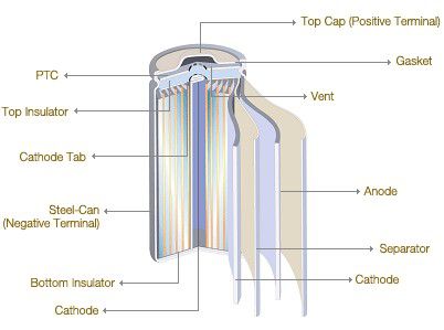
Spiral Wound Electrodes
Spiral Wound Electrodes, also called Jelly-roll or Swiss-roll construction. In the quest for higher current carrying capacity, it is necessary to increase the active surface area of the electrodes, however the cell case size sets limits on the size of electrodes which can be accommodated. One way of increasing the electrode surface area is to make the electrodes and the separator from long strips of foil and roll them into a spiral or cylindrical jelly-roll shape. This provides very low internal resistance cells. The downside is that since the electrodes take up more space within the can there is less room for the electrolyte and so the potential energy storage capacity of the cell is reduced. This construction is used extensively for secondary cells. The example above shows a Lithium-Ion cell but this technology is also used for NiCads, NiMH and even some Lead acid secondary cells designed for high rate applications. Spiral wound construction not limited to cylindrical shapes. The electrodes can be wound onto a flat mandrel to provide a flattened shape which can fit inside a prismatic case. The cases may be made from aluminium or steel. This construction is ideally suited for production automation.
Battery Characteristics
Lithium is the lightest of metals and it floats on water. It also has the greatest electrochemical potential which makes it one of the most reactive of metals. These properties give Lithium the potential to achieve very high energy and power densities in high power battery applications such as automotive and standby power.
Many variations of the basic Lithium chemistry have been developed to optimise the cells for specific applications or perhaps in some cases to get around the patents on the original technology. Lithium metal reacts violently with water and can ignite into flame. Early commercial cells with metallic lithium cathodes were considered unsafe in certain circumstances, however modern cells don't use free Lithium but instead the Lithium is combined with other elements into more benign compounds which do not react with water.
The typical Lithium-ion cells use Carbon for its anode and Lithium Cobalt dioxide or a Lithium Manganese compound as the cathode. The electrolyte is usually based on a Lithium salt in an organic solvent.
Lithium batteries have now taken their place as the rechargeable battery of choice for portable consumer electronics equipment. Though they were expensive when introduced, volume production has brought the prices down.
See more details below.
International Battery Standards
National and international standards organisations were set up to facilitate trade by encouraging greater product interoperability and compatibility as well as setting standards for acceptable product safety, quality and reliability.
Below are listed some of the most common standards applicable to battery applications and some of the organisations who issue them and or carry out quality assurance and conformance testing. InEurope, European standards are gradually being adopted in replacement of the previous national standards.
Copies of the relevant standards can be obtained directly from the issuing organisations or from public libraries.
|
Standards Setting and Safety Testing Organisations |
|
|
Abbreviation |
Name |
|
AENOR |
Asociación Española de Normalización y Certificación (Spain) |
|
ANSI |
American National Standards Institute sponsored by NEMA |
|
AS |
Australian Standard |
|
ASE |
Association Suisse des Electriciens (Swiss) |
|
ASQC |
American Society for Quality Control |
|
ASTM |
American Society for Testing and Materials |
|
ATEX |
Explosive Atmospheres (Safety directive) |
|
BCI |
Battery Council International (Publishes AutomotiveBatteryStandards) |
|
BS |
British Standards |
|
CARB |
California Air Resources Board (Automotive Emission Standards) |
|
CE |
Conformance with EU directives |
|
CEN |
European Committee for Normalisation (Standards Committee) |
|
CENELEC |
European Committee for Electrotechnical Standardisation |
|
CISPA |
International Special Committee on Radio Interference |
|
CODATA |
Committee on Data for Science and Technology (Committee of ICSU) |
|
CSA |
Canadian Standards Association |
|
DEF |
Defence Standards (UK) |
|
DEMKO |
Danmarks Electriske Materielkontrol (Denmark) |
|
DIN |
Deutsches Institut für Normung (German Institute for Standardisation) |
|
ECE |
Economic Commission forEuroperegulations. |
|
EIA |
Electronics Industry Association (USA) |
|
EN |
European Norms (Standards) |
|
FCC |
Federal Communications Commission (USA) |
|
FIMKO |
Finnish Electrical Inspectorate |
|
FIPA |
Foundation for Intelligent Physical Agents (Interoperability standards) |
|
GB |
Guo Biao = National Standard (People's Republic ofChina) |
|
HSE |
Health & Safety Executive (UK) |
|
ICSU |
International Council for Science |
|
IEC |
International Electrotechnical Commission |
|
IEE |
Institution of Electrical Engineers (UK) |
|
IEEE |
Institute of Electrical and Electronics Engineers (USA) |
|
IMQ |
Instituto ItalianodelMarchio de Qualitá |
|
IP |
Ingress Protection |
|
ISO |
International Standards Organisation |
|
ITU |
International TelecommunicationsUnion |
|
JIS |
Japanese Industrial Standard |
|
KEMA |
Keuring van Elektrotechnishe Materialen (Netherlands) |
|
KIST |
KoreanInstituteofStandardsand Technology |
|
MIL |
Military Standards (USA) |
|
MISRA |
Motor Industry Software Reliability Association (UK) |
|
MVEG |
Motor Vehicle Emission Group (EU Emission standards) |
|
NAMAS |
National Measurement Accreditation Service (UKCalibration) |
|
NEMA |
National Electric Manufacturers Association (USA) |
|
NEMKO |
Norges Electriske Materiellkontroll (Norway) |
|
NF |
Norme Française (France) |
|
NFPA |
National Fire Protection Association (USA) |
|
NIJ |
National Institute of Justice (USA) |
|
OSHA |
US Department of Labor - Occupational Safety & Health Administration |
|
OVE |
Osterreichischer Verband für Elektrotechnik (Austria) |
|
PowerNet |
Automotive 42 VoltBatteryStandard |
|
RESNA |
Rehabilitation Engineering & Assistive Technology Society ofNorth America |
|
SAE |
Society of Automotive Engineers (USA) |
|
SEMKO |
Svenska Elektriska Materielcontrollanstalten (Sweden) |
|
SEV |
Schweitzerischer Elektrotechnische Verein (Swiss) |
|
STANAG |
NATO Standards Agreements |
|
STRD |
DTI Standards and Technical Regulations Directorate (UK) |
|
TIA |
Telecommunications Industry Association (USA) |
|
TR |
Technical Report (Used by IEC) |
|
TÜV |
TÜV Rheinland Group (TUV - Technical Inspection Asssociation) |
|
UKAS |
UK Accreditation Service (Assessment of test services)/(Calibration) |
|
UL |
Underwriters Laboratories Requirements (USA) |
|
USABC |
United States AdvancedBatteryConsortium |
|
USNEC |
United States National Electrical Code |
|
UTE |
Union Technique de l'Electriciteé (France) |
|
VDE |
Verband Deutscher Elektrotechniker (Germany) |
|
GeneralBatteryStandards |
|
|
Standard Number |
Title |
|
IEC 60050 |
International electrotechnical vocabulary. Chapter 486: Secondary cells and batteries. |
|
IEC 60086-1, BS 387 |
Primary Batteries - General |
|
IEC 60086-2, BS |
Batteries - General |
|
ANSI C18.1M |
Portable Primary Cells and Batteries with Aqueous Electrolyte - General and Specifications |
|
ANSI C18.2M |
Portable Rechargeable Cells and Batteries - General and Specifications |
|
ANSI C18.3M |
Portable Lithium Primary Cells and Batteries - General and Specifications |
|
UL 2054 |
Safety of Commercial and HouseholdBatteryPacks - Testing |
|
IEEE 1625 |
Standard for Rechargeable Batteries forMobileComputers |
|
USNEC Article 480 |
Storage Batteries |
|
ISO 9000 |
A series of quality management systems standards created by the ISO. They are not specific to products or services, but apply to the processes that create them. |
|
ISO 9001: 2000 |
Model for quality assurance in design, development, production, installation and servicing. |
|
ISO 14000 |
A series of environmental management systems standards created by the ISO. |
|
ISO/IEC/EN 17025 |
General Requirements for the Competence of Calibration and Testing Laboratories |
|
LithiumBatteryStandards |
|
|
Standard Number |
Title |
|
BS 2G 239:1992 |
Specification for primary active lithium batteries for use in aircraft |
|
BS EN 60086-4:2000, IEC 60086-4:2000 |
Primary batteries. Safety standard for lithium batteries |
|
BS EN 61960-1:2001, IEC 61960-1:2000 |
Secondary lithium cells and batteries for portable applications. Secondary lithium cells |
|
BS EN 61960-2:2002, IEC 61960-2:2001 |
Secondary lithium cells and batteries for portable applications. Secondary lithium batteries |
|
02/208497 DC |
IEC 61960. Ed.1. Secondary cells and batteries containing alkaline or other non-acid electrolytes. Secondary lithium cells and batteries for portable applications |
|
02/209100 DC |
IEC 62281. Ed.1. Safety of primary and secondary lithium cells and batteries during transport |
|
BS G 239:1987 |
Specification for primary active lithium batteries for use in aircraft |
|
BS EN 60086-4:1996, IEC 60086-4:1996 |
Primary batteries. Safety standard for lithium batteries |
|
UL 1642 |
Safety of Lithium-Ion Batteries - Testing |
|
GB /T18287-2000 |
Chinese National Standard for Lithium Ion batteries for mobile phones |
|
ST/SG/AC.10/27/ Add.2 |
United Nations recommendations on the transport of dangerous goods |
How are batteries rated? What are volts and amps?
How do we control the quality in-house?
We strongly believe that the quality is the life line of an enterprise, therefore, the quality control are always considered as the most important thing in our production management. We count on our professional and well-trained QC team to effectively control the quality of our products; Our QC Department mainly consists of IQC, IPQC, FQC and QA.
Need battery be activated?
Yes. But this is not the job for users. All of our batteries have been activated in-house after some complicated procedures. What users have to do is only proceeding 3 to 5 times complete charging and discharging before use to achieve for the best capacity condition
How long do batteries last?
The life of a rechargeable battery operating under normal conditions is generally between 500 to 800 charge-discharge cycles. This translates into one and a half to three years of battery life for the average user. As the rechargeable battery begins to die, the user will notice a decline in the running time of the battery. When a battery that originally operated the notebook for two hours is only supplying the user with an hour's worth of use, it's time for a new one.


